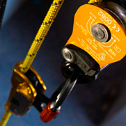
Tensioning a tyrolean with MAESTRO, I’D, RIG
Descenders are effective for tensioning a tyrolean as they provide high tension and an easy release. As with all high-performance systems, it’s essential to know their limits so as not to exceed them.
Warnings
- Carefully read the Instructions for Use used in this technical advice before consulting the advice itself. You must have already read and understood the information in the Instructions for Use to be able to understand this supplementary information.
- Mastering these techniques requires specific training. Work with a professional to confirm your ability to perform these techniques safely and independently before attempting them unsupervised.
- We provide examples of techniques related to your activity. There may be others that we do not describe here.
Descenders are designed for one or two-person loads: the tensions attainable in tyroleans often exceed the normal working loads of these devices. No standard covers tyrolean usage, so it is not included in the devices’ Instructions for Use. Note: a tyrolean differs from a lifeline covered by the EN 795 type C standard.
The tests described below aim to study three main questions:
- Can the effectiveness of descenders in tensioning a tyrolean lead to loads that are dangerous for the anchors or other system elements?
- How does the sag under load change depending on the initial tension of the tyrolean?
- Should we worry about exceeding the descenders’ capacities in case of excessive tension on a tyrolean?
The results show that the maximum measured loads stay below the damage threshold values of the anchors, rope or descenders. However, in some cases the descenders became unreleasable. The tests show that the initial tension placed on the tyrolean has a major influence on the forces in play during its use, while providing very few practical benefits. Notably, the sag under load doesn't change much with a higher initial tension. So it's advisable to avoid over-tensioning a tyrolean: tensioning with the weight of one person on a 3:1 pulley system will be sufficient in most cases.
1. Various tensioning systems
Depending on the position, the rope diameter and the duration of the pull, one person alone can pull 10-20 kg with one hand on the rope, 20-40 kg two-handed with the feet securely braced on the ground, and up to the person’s own weight if the system allows him/her to hang on the pull strand.
Various types of pulley systems enable pulling with mechanical advantage; here is a non-exhaustive proposal of tensioning methods suitable for tensioning a tyrolean with descenders.
Systems that depend on the strength of the operators:
Simple pull by 3-5 persons
1-2 persons pulling on a 3:1 pulley system
One person pulling on a 5:1 pulley system (JAG SYSTEM)
Systems using the mass of the operators:
The advantage of these systems is that they are independent of the operators’ strength and/or energy level and offer good repeatability of tension from one situation to the next.
One person suspended on a 3:1 pulley system
(directional on a RESCUE pulley)
Two persons suspended on a 3:1 pulley system
(directional on a RESCUE pulley)
2. Study of tensions generated in a real world situation.
The first tests were designed to determine the actual tension generated with realistic tensioning systems in the field and to compare the release capacities of different devices depending on these tensions.
Tests done on a 25 m tyrolean on AXIS 11 mm rope, tensioned with one or two 85 kg operators
- The loads on the anchors are the sum of the initial tension and from 100 % to 130 % of the mass hanging on the tyrolean. With a 250 kg mass, an excessive initial tension generates loads greater than 5 kN.
- With I’D and RIG, releasing is difficult when the tension exceeds 5 kN. It's necessary to force the handle and releasing the tension is hard to control, which can present a risk for the load: if released too quickly, it can hit the ground or an obstacle.
- Only the optimization of the sag under load may necessitate a high tension. In all other cases, a tension of less than 2 kN is recommended to avoid overloading the anchors and to facilitate release. This tension is obtained by one person pulling on a 3:1 pulley system.
Notes:
- For releasing, a directional carabiner was installed at the anchor each time in accordance with the Instructions for Use (except for the MAESTRO, which has an integrated external brake).
- During testing, the load on the rope clamp used in the 3:1 pulley system (BASIC) was measured, to ensure there was no risk of it tearing the rope during tensioning. The measured load never exceeded 3 kN, below the values which could damage the rope with this device. 3 kN is a value that is beyond normal usage for the BASIC, which is acceptable while tensioning because no user is loading the tyrolean at this stage.
3. Change in sag with tension
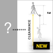
One of the only reasons to highly tension a tyrolean is to reduce the sag under load.
Note: nylon rope has a higher elongation when wet. The sag values would thus be different in wet conditions as AXIS and VECTOR have nylon cores.
Tests done on a 14 m tyrolean using AXIS 11 mm and VECTOR 12.5 mm rope with MAESTRO at the head of the tyrolean.
Tests done with the tension pre-calibrated to repeatable values.
- We see that a very high tension only reduces the sag by 60-80 cm , but significantly increases the load on the anchors.
- If the situation requires reducing the sag, it is without doubt more appropriate to double the tyrolean to share the load over two systems, or to find higher anchors.
4. Exceptional case study: fall tests on a tyrolean
Falling on a tyrolean is a rare event.
The scenario commonly considered is the case where a carriage tyrolean breaks and the load falls onto a second tyrolean installed as a back-up. However, it’s likely that the back-up tyrolean is partly loaded during use, due to the sag of the carriage tyrolean. So the fall distance should not be significant.
The tests were done with a more severe fall than is realistic.
Test done on a 14 m tyrolean on AXIS 11 mm and VECTOR 12.5 mm rope.
Tests done with the tension pre-calibrated to repeatable values.
Test n° 1: change in loads and maximum sag in a fall, depending on the initial tension of the tyrolean
- We see that the loads on the anchors increase significantly with the initial tension.
- The measured load values stay below the breaking strength of commonly used anchors (e.g. 15 kN minimum for COEUR BOLT in the certification tests). And as anchors are generally doubled or tripled in use, anchor integrity should not be jeopardized.
- Beware with a more static rope: the loads on the anchors could increase significantly. We can already see a significant difference between AXIS et VECTOR with the first at 3 % elongation and the second at 2.8 % (as per the EN 1891 test protocol).
Note: test with 3 kN initial tension not done on MAESTRO L and VECTOR 12.5 mm, as the loads on the anchors would likely be too high for our test structure.
Test n° 2: behavior comparison of various devices with an average initial tension of 2 kN
- All falls were stopped despite the severity of the test fall.
- The loads attained mandate the retirement of all system elements used in these falls, even if they show no apparent deterioration.
- WARNING: rope slippage in the devices must not be considered a means of absorbing the energy of a fall (even if that is what actually happens). This slippage cannot be precisely calibrated and could vary greatly depending on the situation (device and/or rope worn and/or wet and/or dirty...). If you are concerned about a dynamic event on your tyrolean, it is better to use more anchors or to modify the setup rather than relying on rope slippage for your safety.
- The rope slippage observed in the I’D and RIG descenders is consistent with the values measured in the laboratory for these devices (e.g. slippage starting at 6.4 kN on I’D S and AXIS).
- During lab tests on the MAESTRO, slippage was measured starting at 10.7 kN on AXIS and more than 11 kN on VECTOR. So it’s consistent that there was no slippage here with values less than 10 kN. In the event of a harder fall, or one on a more static rope generating higher forces, there would also be rope slippage in the MAESTRO.
- During the test on the RIG with 2 kN initial tension, sheath breakage is what contributed to shock absorption (instead of slippage in the device). A comparative test was done with an initial tension of 1 kN: the rope slipped 44 cm in the device and was marked; the force at the anchor was measured at 8.2 kN. So we see that this very severe fall exceeds the RIG's capacities. This device should only be used for tyroleans intended for single-person use, or those designed to ensure that accidental overload cannot occur.
- Is a stopper knot necessary when setting up a tyrolean?
- If the descender is correctly installed (handle turned down, no interference with external objects), a stopper knot is not necessary for proper device function. During the tests, no uncontrolled rope slippage occurred: all devices stopped the fall. However, a stopper knot can be considered an additional precaution to deal with any eventuality.
A stopper knot can have two separate functions:
- Mitigate accidental release of tension in the tyrolean due to mishandling by the operator.
- Prevent the mass from falling if the rope slips in the device (e.g. if a worn device is used).
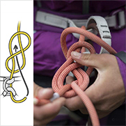
If the knot works, it will jam against the descender. It is thus preferable to tie a knot that is releasable under load, like the slip knot shown below.
For the stopper knot to be effective before the tyrolean completely slackens, it must be tied as close to the descender as possible.
It is also possible to take into account the slippage values recorded during the tests by positioning the knot more than one meter from the descender. However, one meter of rope represents a major loss of tension in the tyrolean and a consequent increase in the sag under load. Placed one meter from the descender, the knot becomes far less effective in its most likely function, which is to mitigate mishandling by the operator.


